Galvanic CP – Magnesium Anodes
Magnesium has got a very electronegative potential compared to other sacrificial anodes and self corrosion rate is too much, if not alloyed. Other impurities particularly iron and other heavy metals can significantly affect the efficiency of the Mg anodes. The addition of zinc causes the Mg anode to corrode homogenously, at the same time, reduces the sensitivity of the anode to other impurities that is just described above.
The most common type of Mg anodes are high-potential and standard type (AZ-63). The high-potential Mg anode has a advantage of relatively high electronegative potential by adding small percentage of manganese to the alloy.
As Mg anode has the highest driving potential compared to other galvanic anodes, makes it better to use in high soil resistivity environments and fresh water. In addition to this, Mg anodes are not pollute and does not contaminate the electrolyte as it is also used in potable water tanks internal galvanic cathodic protection.
The Mg anodes are also useful in combination of usage with other (low potential) galvanic anodes. Because it has high driving potential than, for example, aluminum; which supports and speeds up the initial polarization of the structure.
Type of applications with magnesium anodes are;
- Temporary protection of buried pipelines
- Protection of well coated buried pipelines
- Internal protection of water tanks
- Protection of small marine structures
- “Hot spot” locations for buried & submerged steel structures
- Magnesium anode is suitable to be used in soil, mud, fresh water, brackish water and sea water.
For buried applications, the bare Mg anode is assembled with cable, sealed with epoxy resin and packaged in a cotton bag.
Composition of Backfill
- Gypsum 75%
- Bentonite 20%
- Sodium Sulphate 5%
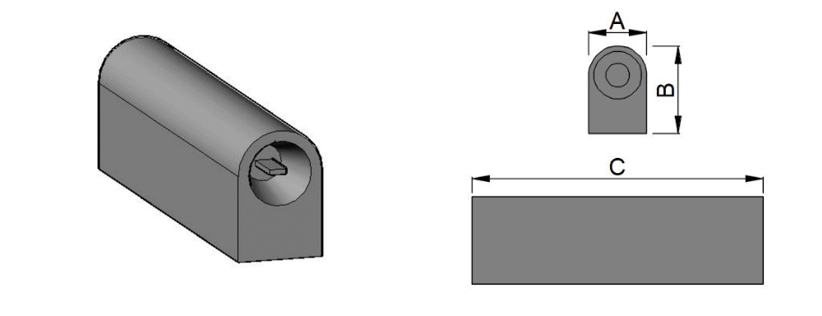
KORTEK standard production and main stock of magnesium anodes for buried structure applications are as below;

| Product Code | Bare Anode Weight | Width - A (mm) | Height - B (mm) | Length - C (mm) | |
|---|---|---|---|---|---|
| Lb | Kg | ||||
| MG-D01 | 3,5 | 1,58 | 84 | 73 | 270 |
| MG-D02 | 5 | 2,26 | 87 | 78 | 270 |
| MG-D03 | 10 | 4,5 | 100 | 100 | 290 |
| MG-D03 | 17 | 7,7 | 140 | 110 | 510 |
| MG-D04 | 22 | 10 | 140 | 120 | 595 |
| MG-D05 | 32 | 14,5 | 145 | 145 | 600 |
| MG-D06 | 44 | 20 | 138 | 162 | 800 |
| MG-D07 | 60 | 27,2 | 80 | 155 | 1500 |
| ALLOY COMPOSITION | ||
|---|---|---|
| Metal | Standard | High Potential |
| Aluminum | 5.30 - 6.70% | 0.01% max |
| Zinc | 2.50 - 3.50% | - |
| Manganese | 0.15 - 0.70% | 0.50 - 1.30% |
| Silicon | 0.10% max | 0.05% max |
| Copper | 0.02% max | 0.02% max |
| Nickel | 0.002% max | 0.001% max |
| Iron | 0.003% max | 0.03% max |
| Other Impurities | - | 0.05% max |
| Total | 0.30% max | 0.30% max |
| Magnesium | Balance | Balance |
| ELECTROCHEMICAL PROPERTIES | ||
|---|---|---|
| Properties | Standard | High Potential |
| Open Circuit Potential wrt Cu/CuSO4 | 1.50 - 1.55 Volts | 1.70 - 1.75 Volts |
| Output Capacity | 1200 A.h/lg | 1100 A.h/kg |
| Current Efficiency | 50% | 50% |
